To promote your account to uploader you need to accept the following terms and conditions
TERMS OF USE OF THE WEBSITE SKRIWARE FOR UPLOADERS
This document defines the legal (contractual) relationship between the Uploader and the Administrator, as well as the legal (contractual) relationship between the User and the Uploader.
I. Definitions
Administrator - Skriware spółka z ograniczoną odpowiedzialnością with its seat in Warsaw, address: ul. Wołodyjowskiego 45, 02-724 Warszawa, entered in the Register of Entrepreneurs by the District Court for the Capital City of Warsaw, 13th Commercial Division of the National Court Register under entry No. KRS 0000540128.
Website - a group of connected web pages, made available on the Internet at www.skrimarket.com.
User (You, Your) - each person who uses any functionality of the Website and/or has signed in to the website.
Uploader – an individual or an entrepreneur who sells or shares for free via the Website Models owned by them.
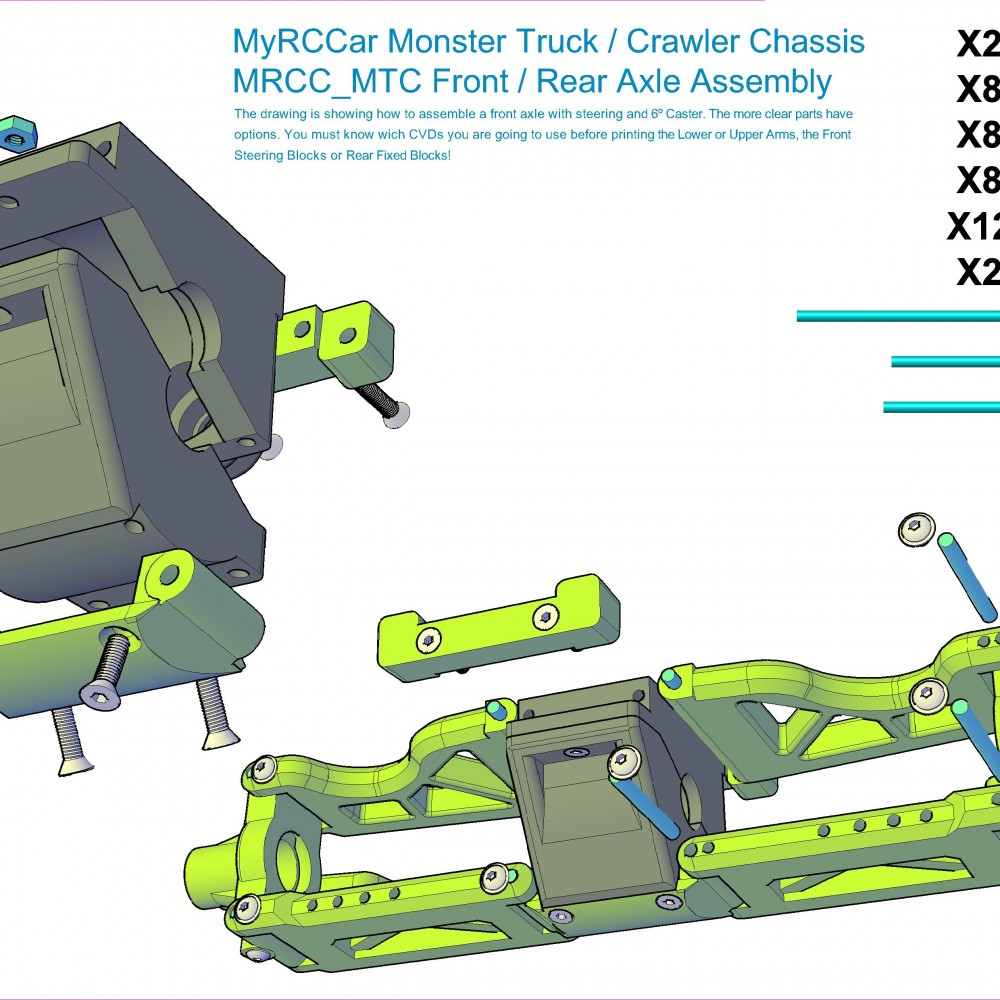
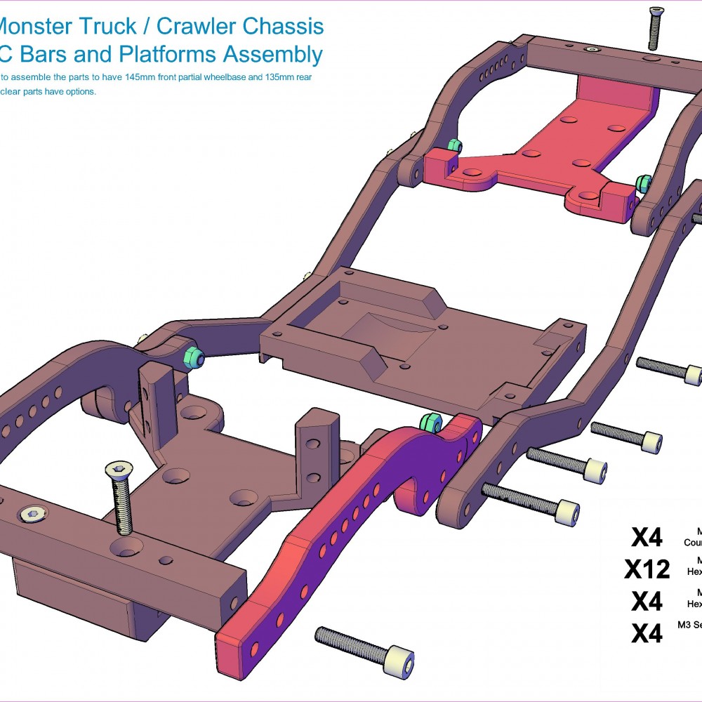
Model – a file with a model for a Skriware 3D printer.
Privacy Policy - a set of personal data processing and data privacy protection rules applied by the Administrator to Users and Uploaders.
Account - an account maintained on the Website for the User, with which the User
may use the services offered by the Website and use the Website’s full functionality.
Medium – a material or a tool in which the User (or the Uploader, or the Administrator) can store information sent to them by the Administrator or the Uploader in a manner that allows for the future access to information during a period which is appropriate for the purposes for which such information is used, and which allows for the restoration of the stored information in the same form.
II. General provisions
1. You hereby state and represent that you accept all the provisions of the Terms of Use and the Privacy Policy without any reservations.
2. Uploaders who are unable to enter into a legal binding agreement with the Administrator or a User, or those who are forbidden to use services provided by the Website due to restrictions applicable in the country or in the region, including the current country of residence of the User and the place where the User is using the services, should not use the Website. You hereby state for the Administrator that you are eighteen (18) years old or older (or that you have reached other age which, pursuant to the law of your country, entitles you to enter into legally binding contracts), you have full capacity to enter into legal transactions and that you agree to the terms and conditions set forth herein. If you act in the name and on behalf of a third party who is a so-called imperfect legal person, you shall hereby state to the Administrator that you are authorized to incur obligations under this agreement on behalf of and for such a person, and your acceptance of these Terms of Use shall mean acceptance of these Terms of by the third party.
3. The Administrator reserves the right to change and modify these Terms of Use, including to add new or delete existing provisions, which the Administrator may do at their own discretion, at any time, by posting the changes made hereto on the Website. That is why, you have the obligation to regularly check if the Terms of Use have not changed. If you continue to use the Website after any changes have been posted and you have not terminated the agreement, it shall mean that you have accepted the changes. Unless the other provisions provide for otherwise, modified Terms of Use shall enter into force automatically thirty (30) days as of the date on which the changes were posted on the Website. When posting any changes, the Administrator has the obligation to indicate which provisions have been amended, added or deleted. The Administrator shall also send information about changes to the Terms of Use to Uploaders’ email addresses. The version of the Terms of Use applicable before a change was made (the existing version) shall apply to any agreements made by and between the User and the Uploader before the change to the Terms of Use was made and which are to be performed after the modified Terms of Use have entered into force.
4. Uploaders, using the Internet or otherwise, may conclude with the Administrator a separate agreement on some rights and obligations between them and the Administrator (Additional Provisions). Should there be any disagreement or discrepancy between these Terms of Use and the Additional Provisions, the Additional Provisions shall prevail unless the Additional Provisions provide for otherwise.
5. For contractual purposes, you agree to communicate with the Administrator and to receive information via email.
6. Within the Website – as regards agreements made by and between the Uploader and the User - the Administrator provides only hosting services. As part of such services, the Administrator only makes ITC infrastructure available to act as an intermediary in data transmission and for Users and Uploaders to store and share their data.
7. The Administrator shall not permit and agree to any breach by Users and Uploaders of any laws and regulations, and third-party rights which shall include but not be limited to, copyrights, industrial property rights or personal interests. With exceptions provided for in these Terms of Use, any data, which shall include but not be limited to Models, is shared by Users and Uploaders at their own responsibility and risk and they assure that they have any rights thereto, which include but are not limited to sharing data, making it public or distributing it.
8. Any texts, graphic materials, interactive functions, logos, photographs, files, software and all other materials within the Website, except for materials transmitted, shared, or posted by Users and Uploaders, as well as selection, organization, coordination, compilation of materials and the overall look and nature of the Website constitute intellectual property of the Administrator. They are protected under copyrights, rights to designs, patents, rights to trademarks and other laws and regulations, including international conventions and property rights. All such rights are reserved to the Administrator. All trademarks and trade names are the property of the Administrator. Without the Administrator’s express consent, neither the User nor the Uploader may sell, distribute, copy, modify, perform, display or broadcast to the public, publish, edit or adapt such items, license them, create derivative works thereof or use them in any other manner.
9. The Administrator shall ensure the possibility to enter into and complete electronic transactions between the User and the Uploader, which includes but is not limited to granting licenses to Users by Uploaders for the use of a Model. The Administrator is not a party to the agreement between the Uploader and the User – the Administrator only provides Uploaders and Users with certain assistance and administrative services.
10. As regards each agreement executed on the Website, you agree to the provision of the performance before the end of the term for termination.
11. You shall not have the right to terminate any and all agreements which you enter into on the Website as regards licensing the specific Model from the specific Uploader.
12. As regards Uploaders being the consumers from the European Union, in relation to agreements concluded with such users via the Website, the Administrator performs their information obligations to the Uploaders pursuant to the relevant laws and regulations.
13. All confirmations required under applicable laws and relations will be sent to the Uploader’s email address.
14. You agree to confirm or share certain data in order to, in case of any doubts, determine their place of residence, registered office or place of ordinary stay, which is connected with the Administrator’s obligation to complete reporting obligations and activities related to Value Added Tax, in particular under Article 58 of the Directive 2006/112/EC of the Council and Implementing Regulations of the Council (EU) No. 282/2011 and No. 1042/2013.
III. Use of the Website
1. You must use the Website pursuant the provisions of these Terms of Use and applicable laws and regulations, in accordance with good practices and the rules of social conduct. The Administrator shall act in the same manner when performing their duties.
2. If you learn of any breach of the provisions hereof by another User, Uploader or any other person, you have the obligation to promptly notify the Administrator thereof.
3. You state and represent that you have read these Terms of Use, including the Privacy Policy and accept all provisions thereof.
4. The technical condition for your use of the Website is to have a work station equipped with an operating system and Internet access, and standard software required to view web pages.
5. To ensure proper operation of some of the Website’s functionalities, it may be necessary for you to provide a modern browser with support of Java Script, decompression software and cookies.
6. To access some of the Website functionalities, you have to sign up for the Website
IV. Obtaining Uploader’s status. Uploader’s Account
1. In order to obtain the status of an Uploader, you must first sign up for the Website and create a User’s Account. Then you must click on the appropriate icon to get the Uploader’s status, accept these Terms of Use and provide additional details via the appropriate form.
2. Existing User’s Account becomes at the same time the Uploader’s Account which includes additional information, i.a. about the accumulated amount of remuneration paid to you by other Users.
3. The Administrator shall have the right to verify Uploader’s details by requesting Users to present relevant documents, copies or scans confirming thereof, etc. In particular, the Administrator may request a scan of an identity document. The documents (or scans or copies thereof) should be submitted within 14 days as of the date on which the Administrator made a request to the person who wanted to sign up for the Website. A failure to provide the said documents (or scans or copies thereof) may be a reason for the refusal to the request for the Uploader status. The Administrator may also request relevant documents (or scans or copies thereof) after you sign up – in this situation your failure to submit the documents (or scans or copies thereof) may provide a ground for blocking your Account.
4. When signing up on the Website, you confirm that you have read and accepted all provisions of these Terms of Use, including the Privacy Policy and that you agreed to the following:
- processing of personal data by the Administrator during the sign-up process on the Website now and in the future – so that the Administrator can provide services available on the Website and to follow the notice and takedown procedure described in clause XIV below, in particular to provide the User’s contact details to a person whose rights have been infringed, as well as for the Administrator to contact Users, and for marketing purposes, including sending commercial information and advertising materials to the User.
5. The Administrator shall have the obligation to provide confirmation of execution of the agreement with an Uploader from the European Union, who is a consumer, on a Medium within a reasonable period of time as of the execution of the agreement. Such confirmation should include information required under the applicable laws and regulations unless the Administrator provided the Uploader with the information on a Medium before the agreement was executed.
6. You must take care that a valid email address is always assigned to your Account on the Website.
7. Your Account is made available to you by the Administrator free of charge and allows you to use the service offered on the Website and provided by the Administrator, which is possible from any place via the Internet. You shall bear any costs connected with Internet access at the rate under the agreement with your operator.
8. As part of actions taken if the rules of these Terms of Use or provisions of the law are infringed, the Administrator shall have the possibility to apply the following sanctions against you:
- warning,
- restriction of use of the Website,
- temporary block on the Account,
- full block on the Account.
9. The Administrator reserves the possibility of temporary interruptions in access to the Website or the Account, which may be caused by modernization works or technical problems. In the event of technical problems, the Administrator agrees to resolve them as soon as possible.
10. You agree that the Administrator may send you commercial information and advertising materials (in particular to your email address) by checking the relevant icon during the sing-up procedure. You may cancel this consent at any time by sending a relevant request to the Administrator's email address.
V. Fees
1. The Users shall not be charged with any fees for signing up on the Website. Only fees for using the selected payment channels shall apply. Users are informed of the amounts of such fees on the payment selection page. The Administrator shall charge its commission to each price (license fee) and transfer the remaining amount to the Uploader. The amount of commission for granting license on the Website may differ depending on the type of payment operator which enables the transaction. The Administrator shall also collect fees for payments made to Uploaders. This fee is necessary mainly to cover the fee that bank or payment operator charges the Administrator in relation to the payment. The fee shall be added and displayed after the User choses a payment method to complete the Model license transaction.
2. Prices for a given Model do not constitute a part hereof and, as long as the User does not purchase a given Model (a license to use it; and therefore, before a license agreement is made), the prices may change.
3. You shall calculate each price (license fee) individually; however, subject to the following sentence, it shall not be lower than USD 0.01 and higher than USD 100. Further, the User may share their Model on the Website free of charge.
4. To the fee referred to in subclause 1 above, the Administrator may add the amount of value added tax by applying the VAT rate applicable in the country of residence, seat or habitual residence of the Uploader in the territory of the European Union, which is connected with the fulfillment of Adminstrator’s value added tax obligations in accordance with the Community law, in particular in accordance with the acts referred to in Article II, item 14.
You agree that the Administrator may add to the sales price referred to in subclause 1 above the amount corresponding to the amount of value added tax by applying the VAT rate applicable in the country of residence, seat or habitual residence of the User non-engaged in economic activity in the territory of the European Union, which results from the Adminstrator’s value added tax obligations in accordance with the Community law, in particular in accordance with the acts referred to in Article II, subclause 14.
In the case discussed in the previous sentence, the commission fee charged by the Administrator is calculated from the sales price which does not include the amount of value added tax.
5. All fees are expressed in USD, otherwise any change shall be communicated. You have the obligation to promptly pay any fees and taxes imposed on you and related to your use of services provided via the Website. In particular, you agree to pay by yourself any applicable taxes, fees, etc. amounts due in relation to the funds received under agreements concluded via the Website, if any.
6. Services (or other functionalities contained in the Website) may be different depending on the country or the region. The Administrator is not able to ensure that a service, a certain type of functionality or range will be fully accessible to all Uploaders.
7. You accept the fact that Users may choose payment method from those available on the Website, i.e. via PayPal. All payment methods are described on the Website.
8. The Uploader agrees this way to payments made by the Users via websites using those payment systems, and states that they have read the terms of use available on the pages of those websites (in particular PayPal) and accepts the provisions contained therein. To the extent permitted by law, the Administrator shall not be held liable to the Uploader for any problems with making payments for reasons attributable to the owners of the above websites, which shall include but not be limited to delays in the completion of payments or inability to make a payment for technical reasons. In such an event, you should contact the operator of the relevant payment website in accordance with the procedure and the rules set forth in the terms of use of the website. If a payment is not accepted for reasons attributable to the Administrator, you should inform the Administrator thereof by sending an email to the following email address: [email protected]
9. You agree that the Administrator may disclose your personal details such as your first name, surname, address and other data such as the number of your bank account, to the above payment operators, and you give your consent to the data processing by the payment operators to complete payment transactions between the User and the Uploader.
10. You represent that you are not a goods and services tax (VAT) payer. If you become a VAT payer or you already are a VAT payer, you have the obligation to provide any data which the Administrator may need to prepare a VAT invoice, in particular your VAT identification number. The invoice will be sent to your email address.
VI. Uploader’s commission fee and Administrator’s obligations
1. Provided that they meet the requirements set out in these Terms of Use, the Administrator shall enable any Uploader to sell their license via the Website.
2. If nothing else is stated in these Terms of Use, you may sell via the Website only the license for the Model that you own (to which you own applicable copyright, patent rights, etc.). Licensed Models are not stored on tangible media.
3. Subject to section V, subclause 3 above, you determine the license sales price (license fee) of a Model, which you intend to share via the Website. Subject to section V, subclauses 1 and 2 above, the Administrator shall deduct their commission fee and other possible fees, if applicable, from the price paid by the buyer.
4. The commission fee charged by the Administrator to the Uploader is 30% of the license sales price (license fee).
5. When issuing a Model for sale on the Website, you give your consent to its licensing under the conditions specified in the Terms of Use for every User who pays for it, and the act itself constitutes a sales offer within the meaning of the civil law. The offer is binding for an indefinite period of time, but no longer than to the moment when a User buys a given Model. So long as no User accepts the offer, you may change the price. If the price is changed, the provisions of subclause 3 above shall apply directly. You acknowledge and accept that prices and descriptions of Models are open information, available to all visitors to the Website. You may also change the licensing of a given Model from free to paid, and vice versa.
6. Moreover, the parties agree that the remuneration due to the Uploader and paid by the Users shall be paid by them through a payment type of their choice (e.g. PayPal) to the bank account of the Administrator. The Uploader hereby gives their unconditional and irrevocable authorization to collect due amounts from Users to their bank account. From the funds collected in the bank account, the Administrator shall deduct the rightful commissions and other possible charges by leaving the amount corresponding to that remuneration on their account, and transfer the rest to the bank account of the Uploader. The transfer of remuneration for the previous month to the Uploader shall take place once a month by the 10th of the following month, except that the Administrator shall transfer funds earned by the Uploader if, as of the date of transfer, the amount is at least USD 10. The funds shall be transferred to the PayPal account of the Uploader; therefore, you have to have such an account in order to receive them.
7. Commission fee paid by the Uploader to the Administrator is non-refundable, in particular, the commission fee shall not be refunded by the Administrator in a situation where amount settled under the present Terms of Use paid by the User to the Uploader for a Model would have to be returned by the Uploader to the User for any reason. Due to the non-refundable character of the commission fee, the Uploaders is not entitled to any claim for compensation against the Administrator. Moreover, the Administrator may withhold in their account the amount covering outstanding remuneration, contractual penalties, the costs which the Uploader is obliged to cover or compensation payable by the Uploader.
8. The provision in subclause 7 above does not apply to Uploaders being consumers in the European Union. In their case, the Administrator shall initiate an investigation (in particular the complaint procedure referred to in clause XVI below), which aims to establish the reasons for which a User requests a refund, and depending on the results of this procedure, the money shall be returned by the Uploader (including not transferring the funds from the bank account of the Administrator to the bank account of the Uploader and returning them to the User), or shall not be returned to the User, who shall be entitled to ascertain their claims against the Uploader before a court or in any other way.
9. Except as explained above, the Administrator does not have any power to manage or dispose of the funds paid by the User for the purchase of a Model from the Uploader.
10. Model descriptions shall be prepared by the Uploader.
VII. Adding Models to the Website
1. Each Uploader has the right to put up for sale an arbitrarily selected number of Models.
2. As an Uploader, you are required to upload the Model into your Account as an .obj or stl. file. The inability to meet this obligation may prevent uploading the Model on the Website or cause the Model to be removed by the Administrator.
3. The Uploader accepts that the Models uploaded into the Website are intended only for printing on Skriware 3d printers. The Uploader undertakes to take all necessary steps in order to enable the User to make a correct Model printout.
4. After uploading the file referred to in subclause 2 above, the Administrator shall adapt it for printing on a Skriware printer, and shall make it publicly available via the Website along with the price fixed by the Uploader in accordance with the provisions of these Terms of Use, to which the Uploader hereby gives their consent
5. The condition for including the Model in the Website is the possibility of printing it on the Skriware printer.
VIII. License
1. You accept the fact that by paying for the opportunity to use a Model shared by you on the Website a User purchases from you a non-exclusive, single, non-transferable (without the right to sublicense), world-wide license for the Model.
2. The User is entitled to use the Model as follows:
- covert the Model to the language of the Skriware printer and print any number of 3D copies included in the Model,
- temporarily multiply the Model digitally in the memory of the Skriware printer/memory of their computer to make a printout.
3. You acknowledge that User cannot save the Model in the memory of their computer, or on any other storage media (in particular, to make printouts on the basis of the model later). The User can only print the selected number of copies of a 3D model on a Skriware printer once directly from the Website, after they click Print or a similar command. If the User wanted to print the same Model again after the printing process, they would have to buy the license for it again pursuant to these Terms of Use.
4. You accept that the User acquiring the license agrees not to:
- make any changes to the Model,
- try to or save the Model on any storage media,
- share the Model with any third parties,
- modify, distribute, share, including on the Internet, multiply, lease, rent, lend for use, sublicense, change, or translate the Model or the software necessary to make a printout on a Skriware printer,
- tamper with the Model or the software necessary to make a printout on a Skriware printer.
5. You accept that the Administrator does not guarantee to the User that the Model will be defectless, will work properly and that it will meet their expectations or be compatible with their software. The Administrator does not grant statutory warranty for any defects of the Model.
6. You accept that, to the extent permitted by law, the Administrator shall not be held liable to Users for proper operation of the Model (in particular due to the fact that the Administrator is not a party to the license agreement pertaining to the Model), or for any (direct or indirect) damage or lost profits connected with the use of the Model by the User.
IX. Relationships between Uploaders and Users
1. Uploaders acknowledge that transactions may sometimes entail fraud. The Administrator fulfills any obligations to verify both Uploaders and Users, in particular during the User’s registration process, or during payment procedure. However, the Internet does not give a full guarantee that the identity of all parties participating in transactions will be verified. It is recommended that you also follow all the procedures in order to make sure that the intentions of the other parties are true.
2. Each User and Uploader is individually responsible for exercising due care when entering into transactions on the Website and using the services offered via the Website, as well as for following the accepted Terms of Use and meeting other obligations. This shall apply to matters such as the warranty obligation, taxes, commissions and other fees, licenses, insurance or lead time.
3. The agreement between a User and an Uploader shall be concluded when the User’s payment is confirmed with the relevant functionality available in the Website. Any other activities of the parties to the agreement, their mutual rights and obligations are regulated by the relevant laws and regulations.
4. By purchasing a single license for the Model, the User does not purchase any copyright or title to the Model, or to the software related to the use thereof.
5. At the moment of concluding the Agreement, the User shall make a statement to the Uploader that:
- they purchase the Model after making sure that they have the possibility to print it,
- they have a Skriware printer,
- they accept the fact that by paying for the Model, they acquire a license to use it pursuant to the provisions of these Terms of Use,
- they have sufficient funds to make payment to the Uploader,
- they are aware of the fact that by buying the Model they enter into an agreement with a given Uploader and not the Administrator.
6. Each Uploader states and represents to each User and the Administrator that:
a) they have full rights to accept these Terms of Use and the Privacy Policy, to grant licenses and to authorize entities to accept responsibility for their application,
b) when placing any products or services, which include but are not limited to Models on the Website, or when selling them via the Website, the Uploader states and represents that they are free of (physical and legal) defects and any claims of third parties, and that the Uploader has all and any rights to share and sell such products and services, which include but are not limited to title, copyrights, and that the Uploader has any required licenses, rights, permits and consents to use, distribute, share, publish or sell, etc. them, which includes but is not limited to the right to sell them on the Internet, in an online system, as well as that these rights are not restricted in any manner whatsoever,
c) products and services offered by them via the Website, which include but are not limited to Models (a) do not infringe any rights of third parties, including copyrights, rights to trademarks, patent rights, trade secrets, privacy rights, rights of publicity, or any other property rights or intellectual property rights, or (b) do not vilify, slander, defame, or insult any persons or entities, or infringe their rights, including their privacy rights, publicity rights, or any other personal interests.
d) they agree to use the Website and its functionalities pursuant to these Terms of Use, applicable laws regulations, in accordance with rules of social conduct and good practices,
e) they will not engage in any activity detrimental to the good name or reputation of the Administrator, or which could have a negative impact on the Website or products and services sold via the Website,
f) they shall not engage in any action contrary to law, good practices, rules of social conducts or any actions detrimental in any way to the interest of the Administrator or Users,
g) they shall not use the Service to undertake activities related to money laundering or activities posing Administrator at risk of being accused of using the Website to money laundering,
h) they shall waive any rights and claims in respect of the printouts made by the users on the basis of the Model which was purchased from the them.
7. The Uploader is obliged to provide information and documents regarding offered products and services at the first request of the Administrator. Each Uploader is obliged, certifies and bears full responsibility for:
- the accuracy and reliability of the information provided,
- the immediate provision of all information in case of any changes to the data.
8. Additionally, the Uploaders are obliged to certify and bear responsibility for that the products, services and data presented, published and offered by them via the Website meet the following conditions:
- they are correct, true and lawful,
- they are not false or misleading,
- they do not contain any defamatory, deceptive, obscene, vulgar or offensive content, including content discriminating anyone,
- they do not infringe the provisions of these Terms of Use and Privacy Policy,
- they do not infringe any other laws and regulations.
9. In addition, each Uploader is obliged, certifies and bears responsibility for the following:
- while visiting and enjoying the functions of the Website, the Uploader shall undertake all actions in compliance with laws and regulations, to abide by which they undertook,
- they shall treat other Users of the Website appropriately and cooperate with them in good faith,
- all their actions shall be undertaken in accordance with the Terms of Use and additional obligations set out in connection with the Website,
- they shall not use the Website for the purpose of theft, depletion, or misappropriation of User’s money, or otherwise infringe the Terms of Use (by selling stolen goods or paying with stolen credit cards), nor shall they undertake any fraudulent actions;
- they shall not divulge any false information by impersonating a third party, or deliberately mislead others,
- they shall abstain from spamming or phishing (insidiously wheedling confidential information),
- they shall not apply or urge to use any illegal methods and procedures,
- they shall not take part in activities aimed at illegal acquisition and dissemination of user data such as passwords, addresses, etc.,
- they shall not use any computer virus, software, or other methods to damage, destroy, intercept or misappropriate any data, hardware, software or information,
- they shall not affect the integrity and security of information, systems and networks belonging to the Administrator, nor shall they attempt to gain unauthorized access to Website databases,
- they shall not undertake any other actions that may have adverse legal consequences for the Administrator.
10. A Model that does not correspond to the assurances and statements referred to above, in particular those in subclause 6(b)(c) above, may at any time be removed from the Website by the Administrator, and the Uploader accepts the fact and confirms that they shall not put forward any claims against the Administrator due to this fact.
11. Each Uploader is obliged to inform the User in a clear and understandable way, at a moment when the User from the European Union declares their will to enter into a binding contract at the latest, about:
- the main characteristics of service, including its subject matter and means of communication with the User;
- their identification data, in particular of the company, the body which has registered its business, as well as the number under which it was registered,
- the address of the company, email address and phone or fax number, if applicable, under which the User may quickly and effectively communicate with the entrepreneur,
- the address at which the User may file a complaint if it is different from the address referred to in section c) above,
- the total price or the remuneration for the provision of service including taxes, and when the nature of the subject matter does not allow, reasonably assessing, for an early calculation of costs - about the way they are going to be calculated, as well as about the fees for transport, delivery, postal services and other costs, and if such amounts cannot be determined - about the obligation to pay them;
- the cost of using the means of distance communication for the purpose of concluding the contract if the cost of using such means is higher than usual,
- the manner and date of payment,
- the method and date of performance of service by the Uploader and the complaint procedure applied by the Uploader,
- the absence of the right to withdraw from the agreement in the case when the User loses their right of withdrawal,
- the existence and content of warranty and after-sales services and the manner of their implementation,
- the minimum duration of User’s obligations under the agreement,
- the functionality of digital content and technical measures to protect them,
- relevant interoperability of digital content with hardware and software, of which the Uploader knows or should know.
12. The information referred to in subclause 11 above may be communicated to the User by the Uploader through the Administrator, who may only provide this information without introducing any modifications to it.
13. The Uploader shall provide a document confirming the conclusion of an agreement with the User, being a consumer from the European Union, on a Medium within a reasonable time limit after its conclusion. Such confirmation should include information referred to in subclause 10 above unless the Uploader provided the User with the information on a Medium before the agreement was made. The confirmation referred to in this section may also be provided by the Uploader through the Administrator, who may only provide this confirmation without introducing any changes to it.
X. Uploader’s statement
1. As an Uploader, you are solely responsible for all data you transmit, share, distribute and store via the Website and you hereby acknowledge that the Website is only a tool used for transmission and storage of data as part of the hosting services referred to in clause II, subclause 6 of these Terms of Use. Therefore, you are solely responsible for all data you transmit, share and store and the results of the publication thereof.
2. The data you transmit or share may not violate any orders and prohibitions set forth in the “Forbidden use of the Website” clause hereof.
XI. Forbidden use of the Website
As an Uploader, you shall hereby state and warrant that you will not engage in the following activities:
a) you will not upload, create or distribute any data that violates the applicable laws and regulations, provisions of binding agreements or third-party rights (including any trade secrets, any intellectual property rights, copyrights, personal interests or personal data protection rights);
b) you will not post any false or misleading information which could expose the Administrator or any third parties to damage;
c) you will not post, share, transmit or upload on the Website any data, including Models, which is illegal, obscene; which slanders or threats any third parties, any pornographic, vulgar, aggressive, content; any content that insults certain races or nationalities; any hateful content; any criminal behavior; any behavior that promotes fascism, Nazism and other murderous ideologies, any content promoting phonographic or computer piracy, popularizing data security cracking techniques, viruses or any other similar content and materials;
d) you will not pass yourself off as any other person or any other actually existing or fictitious entity, state contrary to the facts that you are associated with any person or entity, or access Accounts of other Users or Uploaders, or give false information on sources, nature, or content of data transmitted via the Website, or mislead other Users, Uploaders or the Administrator in any other manner;
e) you will not use the Website for any other purposes than to use the services offered by the Administrator;
f) you will not bypass or deactivate the Website security;
g) you will not send any spam to other Users of the Website, i.a. advertising and promotional materials, or send commercial information, forwarded messages, announcements, requests for donations for charitable purposes to multiple Users,
h) you will not use the Website for any illegal purposes or to violate national or international laws and regulations, including those on the protection of copyrights, industrial property and other property rights, as well as personal data protection laws;
i) you will not defame, harass, insult, or cheat on Users of the Website, collect or try to collect their personal data or personal data of third parties without their consent, or threaten them.
j) you will not try to break the source code of the Website or any part thereof, or tamper with it in any manner;
k) you will not modify, adapt, or translate the Website, or any part thereof (including the Terms of Use), or create any derivative works based thereon;
l) you will not intentionally interrupt or try to interrupt the operation of the Website in any manner, or prevent other Users or Uploaders from using the Website, which includes but is not limited to placing or distributing viruses or other malicious software like adware, spyware, etc.;
m) you will not undertake any actions in order to read passcodes of other Users or Uploaders, including not trying to guess passwords;
n) you will not transfer or share your Account or any part thereof for payment in any manner,
o) you may not upload any data which includes any personal data of third parties, including Users, on the Website,
p) you may not prevent other Users or Uploaders from using the Website in any manner.
XII. Liability
1. To the extent permitted by law, the Administrator’s liability shall be excluded for:
- any damage resulting from your use of the Website, your access to the Website, or your inability to use the Website for reasons beyond the Administrator’s control;
- any damage caused by viruses, Trojan horses etc., which may be sent to the Website or via the Website by third parties; however, the Administrator shall have the obligation to take immediate actions to mitigate the risk posed by such viruses, etc.
- consequences of acquiring your passcode by third parties if it happened due to reasons attributable to you; such reasons shall include but not be limited to sharing your password with a third party,
- any actions taken by the Administrator in relation to you and connected with your breach of the law of the provisions of the Terms of Use, which shall include but not be limited to a block on the Account or access to the Website, restriction of the use of certain services and functions on the Website,
- any breach of any laws and regulations, or infringement of third-party rights by the Uploader and any consequences thereof, which shall include but not be limited to any damage to third parties caused by Uploaders as result of infringement of copyrights, industrial property rights, etc., in particular for damage caused by transmitting, distributing, publishing or sharing of data to which you do not have a copyright or other required authorization,
- any actions and consequences thereof resulting from your breach of the provisions of these Terms of Use or your giving false data or making false or untrue representations and warranties referred to herein,
- any of your actions taken to collect personal data illegally, and to process it, which shall include but not be limited to sharing personal data of other Users or Uploaders with unauthorized persons,
- any damage, claims, damages, compensation in relation to claims of one User against another User of the Website (exclusion of the Administrator from disputes between Users).
- any damage, claims, damages, compensation, physical and legal defects of products and services, Models in particular, sold by Uploaders via the Website to Users due to the fact that the Administrator is not a party to the legal relation in this situation.
2. In particular, the Administrator shall not be held liable to any third party for your failure to perform or for performing the agreement with the User improperly, the fact that you committed a prohibited act, violated a provision of the law or provided false information, or made false warranties or representations. If any third party files to the Administrator any charges, claims, complaints, petitions, requests, etc. in relation to your conduct referred to in the previous sentence or in subclause 1 above, you shall agree to assume full liability to such parties, which means that you shall bear any related costs incurred by the Administrator or any costs that the Administrator will be obliged to bear in any form, which shall include but not be limited to attorney’s fees, fees, damages, fines, exemplary damages, cash penalties, contractual damages, costs of summons, expenses related to appearance in court or before state or public administration authority, correspondence costs and any other possible costs, fees, etc. Further, if any third party brings any claims against the Administrator for infringement of rights of such persons by you, which shall include but be not limited to copyrights, you shall take the place of the Administrator in the proceedings or shall join the case as an outside intervener. The provision of this subclause shall apply to Uploaders from the European Union to the extent in which it does not infringe consumer rights.
3. Further, the Administrator does not guarantee that the User and the Uploader have the ability and capacity to enter into an agreement via the Website, and in particular that the agreement will be performed. The Administrator shall not be held liable to you for the User’s failure to perform or improper performance of the agreement. The Administrator shall not be held liable to Users for the correctness of statements made by Users or the ability to enter into an agreement with an Uploader via the Website.
4. The Administrator does not grant any statutory warranty or quality guarantee for products and services sold via the Website by Uploaders, and for products or services sold by the Administrator unless consumer protection laws provide for otherwise.
5. To the maximum extent permitted by law, the Administrator does not guarantee and is not responsible for the quality, import, export, distribution, marketing, display and future use of any of the services or products, nor is the Administrator responsible for any potential infringement of third-party rights resulting from the use of any services or products available via the Website.
6. Any liability of the Administrator to Uploaders who are entrepreneurs shall be limited to the amount of USD 500. The above sentence shall not release you from the obligation to prove and document the damage you suffered. You have the obligation to report your claim within 14 days as of the date on which the claim occurred or was noticed. In the countries where limitation of liability towards consumers is permitted, the provisions of the previous sentence shall apply respectively, which means that the Administrator’s liability to them shall be limited for any pecuniary losses to the amount of USD 500.
7. Limitations and liability and its complete exclusion pursuant to the accepted Terms of Use refer to the maximum interpretation permitted by law and shall be in force regardless if the Administrator has been notified of the damage.
XIII. Uploader’s liability
1. The use of reserved trademarks by the Uploaders using the Website must not infringe the protection rights of entities entitled to the trademark and may take place only for description, or information purposes, or to express permitted criticism.
2. The use (even indirect) of copyrighted materials of third parties by Uploaders on the Website may take place only upon the consent of the entitled parties, or only within the permitted use. It is permitted for Uploaders to share (even indirectly) content to which they have copyrights unless it does not infringe any third party rights.
3. The Uploaders shall be held solely liable for infringement of copyright, industrial property rights, personal interests and other rights connected with transmitting, sharing, publishing, distribution, storage, etc. of specific data in a given Model, as well as for the violation of applicable laws and regulations or the provisions of these Terms of Use.
4. The Uploader shall be held liable for any actions or failures to act of any other entity with which they share their Account, or the opportunity to use the services provided by the Administrator, as if they had been their own actions or failures to act.
XIV. Countering breaches of the law (notice and takedown procedure).
1. A person whose rights were infringed by data posted (stored, transmitted, etc.) on the Website by the Uploader shall have the obligation to notify the Administrator thereof (to the following email address: [email protected] or by registered mail to the address referred to in clause I of these Terms of Use next to the definition of the "Administrator"), by indicating and submitting:
a) exact location of the data,
b) the scope of an infringed right,
c) the circumstances and evidence that make the right of action to take legal action in relation to the infringed right probable, together with a statement made under the penalty of perjury about the sole authorization to the data found on the Website, and the lack of authorization of an Uploader (the statement should be submitted in writing to the address referred to in clause I hereof, next to the definition of the term “Administrator”, and a scan of the statement should be sent to the following email address: [email protected].),
d) their contact data which shall include but not be limited to their first name, surname, address of the registered office or place of residence, email address,
e) statement on the consent to the processing of personal data for the purposes of the notice and takedown procedure - the statement should be submitted in writing to the address referred to in clause I hereof, next to the definition of the term “Administrator”, and a scan of the statement should be sent to the following email address: [email protected].
2. After receiving a credible notification referred to in the previous subclause, the Administrator shall immediately block access to the data specified in the notification (which shall include but not be limited to deleting it) and, if possible, the Administrator shall notify the Uploader who placed the data on the Website that the notification has been received and of the charges raised by the third party.
3. The Uploader who received the notification referred to in subclause 2 above may take a position thereon and present evidence that confirms their rights to distribute, share, etc. the data.
4. The Uploader and the person who notified the Administrator that their rights had been infringed shall make effort to resolve the dispute in a loyal and amicable manner as regards their rights to the data posted/shared on the website by the User. If the parties reach an agreement, the data covered by the dispute, depending on the arrangements, will be:
- restored on the Website without any modifications,
- restored on the Website with any modifications agreed by the parties to the dispute,
- deleted from the Website irrevocably.
The agreements of the parties under which it will be acceptable to restore the data on the Website shall require written statements of both parties which shall be signed by authorized persons, and the originals of which shall be sent by registered mail to the address referred to in clause I hereof next to the definition of the term “Administrator”. Until the above statements are sent, the data may not be restored on the Website.
5. If it is not possible to identify the Uploader who shared, distributed, etc. the data of the third party on the Website, the Uploader does not take a position on the notification on the complaint of the third party within 14 days as of the date on which the notification by the Administrator was sent to the Uploader’s email address, or does not submit evidence within this period that they have the right to share, distribute, etc. the data, the data shall be deleted from the Website irrevocably.
6. If an official notice or reliable information on the illegal nature of the data available on the Website is received, the Administrator shall immediately prevent access to the data.
7. The Administrator may also delete certain data or prohibit transmission, sharing, storing, etc. of certain data on its own initiative if the Administrator receives reliable information on the illegality or unlawfulness of the data.
XV. Termination
1. The agreement between the Administrator and you is concluded for an indefinite period of time. Both you and the Administrator have the right to terminate the agreement. There is no minimum period of your obligation.
2. The Administrator terminates the Agreement by deleting the Uploader’s Account or by permanently blocking the Uploader’s access to the Website. The Account may be deleted or the Uploader’s access to the Website may be permanently blocked after 14 days have passed as of the date on which the information including the termination notice/notice on blocking the access was sent to the Uploader’s email address. However, in the event of your gross breach of the provisions hereof, which shall include but not be limited to your infringement of copyrights or personal interests of third parties, the Administrator may terminate the agreement with immediate effect by immediately deleting the Uploader’s Account or permanently blocking your access to the Website.
3. The Uploader terminates the agreement by deleting their Account. You may terminate the agreement with the Administrator within 14 days as of the execution hereof. After 14 days, you may terminate the agreement at any time by ceasing to use the Account, which shall include but not be limited to refusing to accept changes to the Terms of Use, by clicking the relevant link in the settings of your Account or by sending a request for deletion of the Account to the Administrator’s email address. The Administrator shall have the obligation to immediately delete the Account, within 3 days as of the date on which the Administrator received the Uploader’s request. After an ineffective expiration of the above term, the agreement shall be terminated.
4. Any transactions made between you and a User during the notice period shall be valid. Any settlement related thereto shall be made during the notice period or after the termination of the agreement. The same shall apply to the situation where a Model is purchased by the User before the agreement is terminated, and the settlement did not take place before the termination of the agreement.
XVI. Final Provisions. Complaint Procedure.
1. The "Privacy Policy" Appendix shall be an integral part of these Terms of Use binding all registered Uploaders.
2. Any data collected by the Website’s Administrator in connection with the Website’s operation shall be processed pursuant to the Privacy Policy, to which you agree when accepting the Terms of Use.
3. Any communication with the Website’s administration should take place via email to the email address [email protected]
4. Any comments on breaches of the provisions of the Terms of Use by Users may be reported to the Administrator to the following email address: [email protected]
5. You have the right to file complaints about services provided by the Administrator via the Website. Complaints should be filed in the electronic form to the email address: [email protected]. Complaint will be examined within 7 days as of the date on which they are received by the Administrator. A report of an objection in the complaint procedure should include the Uploader who files such an objection, detailed information on irregularities and specification which solution will be the most satisfactory to the Uploader. A reply to a complaint shall be sent to the email address from which the complaint was sent or to any email address given by you.
6. You may not transfer any of your obligations or amount due under this agreement (under these Terms of Use) with the Administrator to any third party without the Administrator’s consent.
7. Any provisions which are held to be invalid or ineffective shall not affect the validity of other provisions. Such invalid provisions shall be replaced with valid provisions which better reflect the economic purpose, intention of the parties and the purpose of ineffective provisions.
XVII. Promotional period
1. In the period before 31 July 2016, the Administrator agrees to grant a coupon for USD 100 to any User who will sign up on the Website, create an Account and buy a Skriware printer during that period.
2. The User may use the coupon by 31 July 2016. The promotion expires thereafter and any unused coupons will not be accepted by Uploaders.
3. Each User may receive and use only one coupon for each Skriware printer purchased. The User is not entitled to pass the coupon to any other User.
4. The coupon may only be used to purchase a Model or Models on the Website.
5. The coupon is not the equivalent of electronic money.
6. It is absolutely prohibited to use the coupon to purchase a Model from yourself. Uploader holding a coupon may only use it to buy a license for a Model of another Uploader.
7. Any attempts to use the coupon contrary to its purpose, any attempts to misuse it, in particular in order to obtain cash from the coupon by the User or causing damage to the Administrator’s assets shall be forbidden. A breach of the above prohibition shall result in immediate deletion of the Account and a ban on any further use of the coupon.
8. The coupon may not be redeemed for a cash equivalent.
9. The amount paid with the coupon shall be transferred to the Uploader without being reduced by a commission fee.